Back to Tech Explorer
Actuator
Angular Motion
Servo Motor Guide with Arduino
A servo motor is a small, geared motor that can rotate to a precise angle and hold its position, rather than spinning continuously like a normal DC motor. It works by reading a pulse-width modulated (PWM) control signal and using an internal feedback loop to move its shaft to the angle that signal represents. Servo motors are widely used in robotic arms, steering mechanisms, camera gimbals, and any project that needs precise, repeatable angular movement.
In this guide, we will explore how the servo motor works, its key features, how to connect it to an Arduino, and example code to get you started on your own angular-motion projects.
Controls
Angle
Input
PWM Signal
Uses
Angular Motion
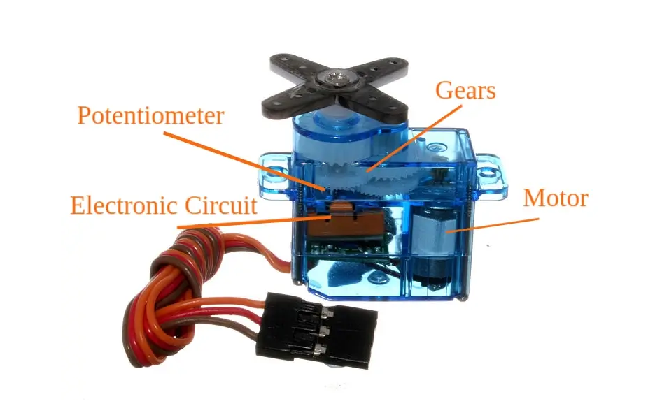
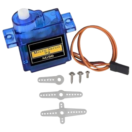
The servo motor is a small, geared motor that can rotate to a precise angle and hold its position, rather than spinning continuously like a normal DC motor. It works by reading a pulse-width modulated (PWM) control signal and using an internal feedback loop to move its shaft to the angle that signal represents.
- Operating voltage: 4.8V to 6V DC (typically powered from 5V)
- Rotation range: approximately 0 to 180 degrees (standard servo)
- Control type: PWM signal, pulse repeated approximately every 20 milliseconds
- Pulse width of roughly 1 to 2 milliseconds sets the shaft angle
- Internal gear train and feedback potentiometer hold the commanded position
- Compact size, commonly used for lightweight positioning tasks
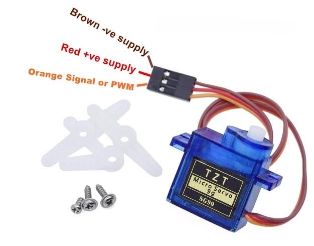
| Wire |
Type |
Description |
| VCC (Red) |
Power |
Power supply (4.8V – 6V) |
| GND (Brown/Black) |
Power |
Ground connection |
| Signal (Orange/Yellow) |
INPUT |
PWM control signal that sets the shaft angle |
How the Servo Motor Works
A servo motor moves its shaft to a specific angle and holds it there, based on a repeating electrical signal it receives on its signal wire.
1
Sending the PWM Signal
The microcontroller sends a pulse on the signal wire roughly every 20 milliseconds. The width of each pulse, typically between 1 and 2 milliseconds, tells the servo which angle to move to.
2
Reading the Pulse Width
The servo's internal control circuit measures the width of the incoming pulse and converts it into a target angle. A shorter pulse commands one end of the range, a longer pulse commands the other end, and a pulse near the middle commands the center position.
3
Comparing with the Current Position
A potentiometer connected to the output shaft reports the servo's current angle back to the control circuit. This is compared against the target angle from the incoming pulse to work out how far and in which direction the shaft needs to move.
4
Driving the Motor to Position
The control circuit drives the internal DC motor through the gear train until the potentiometer reading matches the target angle, then holds that position. This closed feedback loop lets the servo maintain a precise angle even against light resistance.
Using the Motor with Arduino
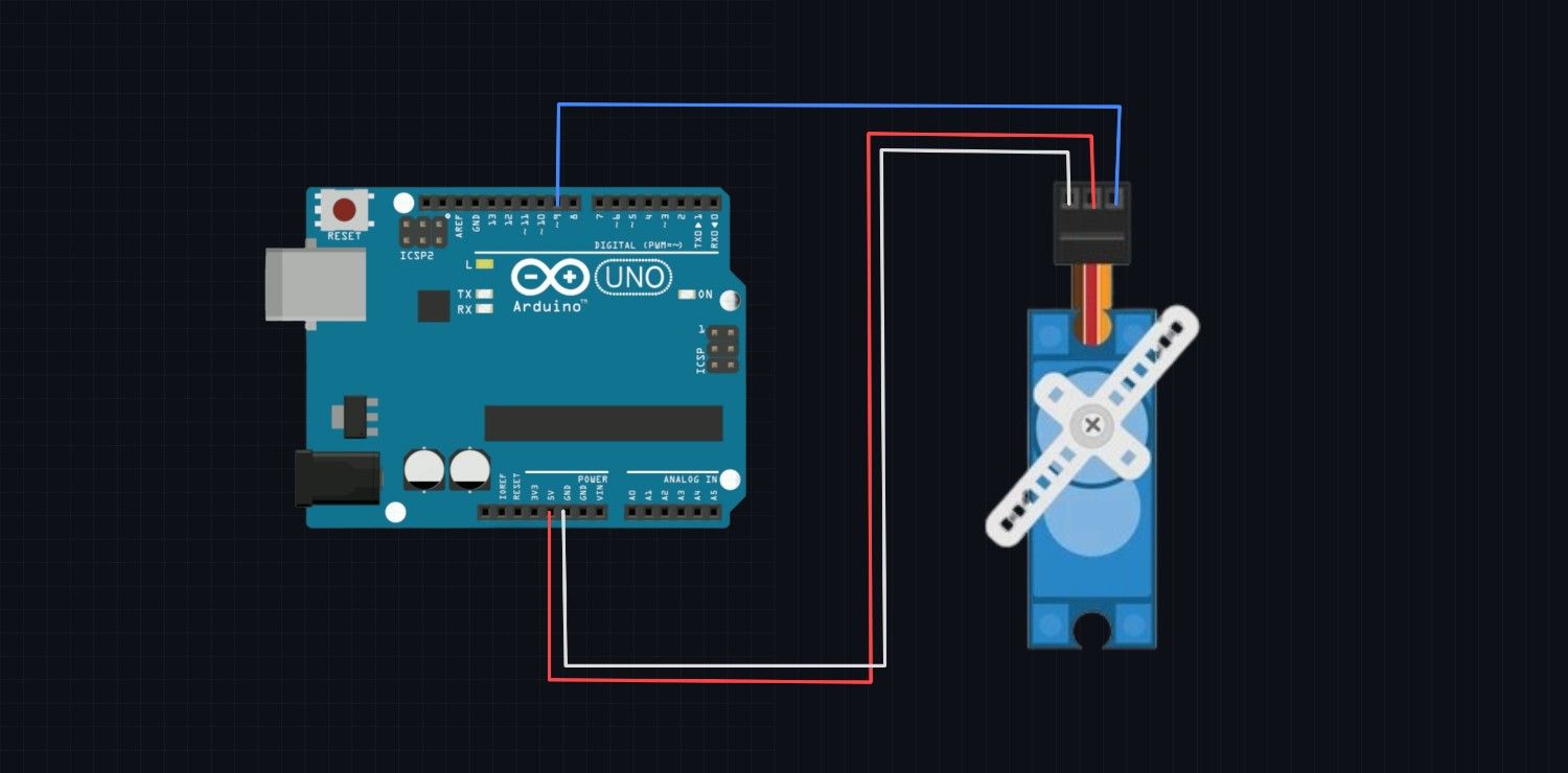
Wiring Servo motor to Arduino
| Servo Motor Wire |
Arduino Uno Pin |
| VCC (Red) |
5V |
| GND (Brown/Black) |
GND |
| Signal (Orange/Yellow) |
D9 |
Arduino Script
#include <Servo.h>

#define SERVO_PIN 9

Servo myServo;

void setup() {
  myServo.attach(SERVO_PIN);
  Serial.begin(9600);
  Serial.println("Servo Motor Initialized...");
}

void loop() {
  // Sweep from 0 to 180 degrees
  for (int angle = 0; angle <= 180; angle++) {
    myServo.write(angle);
    delay(15);
  }

  // Sweep back from 180 to 0 degrees
  for (int angle = 180; angle >= 0; angle--) {
    myServo.write(angle);
    delay(15);
  }
}
The servo motor is a simple and effective way to achieve precise angular movement without needing to build your own feedback control. By reading a PWM signal and comparing it against its own position, it can rotate to and hold a commanded angle. With its easy three-wire interface, it can readily connect to microcontrollers like Arduino using the built-in Servo library for various applications such as robotic arms, steering, and camera positioning. Understanding how to wire and program the servo motor opens up many possibilities for creating interactive and responsive projects.